Showing posts with label Tutorial. Show all posts

Wednesday, April 29, 2015

The Difference Between Bump and Normal Maps

 In cases where it would be inefficient to use geometry to capture minor details like the gaps between bricks or floorboards, another kind of texture map can be used which, for many years, was known as a bump map.


 This image shows three spheres. The first sphere has flat and has no texture assigned to it. The second sphere has a simple checker map assigned to the bump channel. The bump map tells the renderer how to light the model, without affecting the geometry. For many years, the bump map was used to create this extra detail, but often it seemed rather flat and unrealistic, especially if it was used heavily in a model. In succession, normal maps were created, which, by defining a lot more than a bump map, tells a lot more information to the renderer which helps it light the model in a more realistic manner. This is what is applied to the right-most sphere and, comparing the two method it is clear which is the most superior.


These are the textures that were assigned. Bump maps worked in greyscale, where how light or dark an area defined how 'displaced' an area was on the model. Normal maps work a lot differently. By simulating light hitting an object from three different directions, it is a lot more detailed, but also harder to replicate by hand.

 This is a visualisation of a normal map. This model is simply a cube with a torus laid on top. There are multiple lights that are rendered. First, there is a white ambient light. Then, in three directions, lights for the three primary colours are placed. Often blue faces straight down, with red and green being the other two. Finally, lights with the same colour but negative intensity are placed opposite of the directional lights.

However, this is often not how normal maps are generated. There are multiple ways that they can be made.

First of all is the most simple - converting a bump map into a normal map. This is not a perfect method but for most cases it works fine. Programs such as Crazybump and xNormal are able to do this.

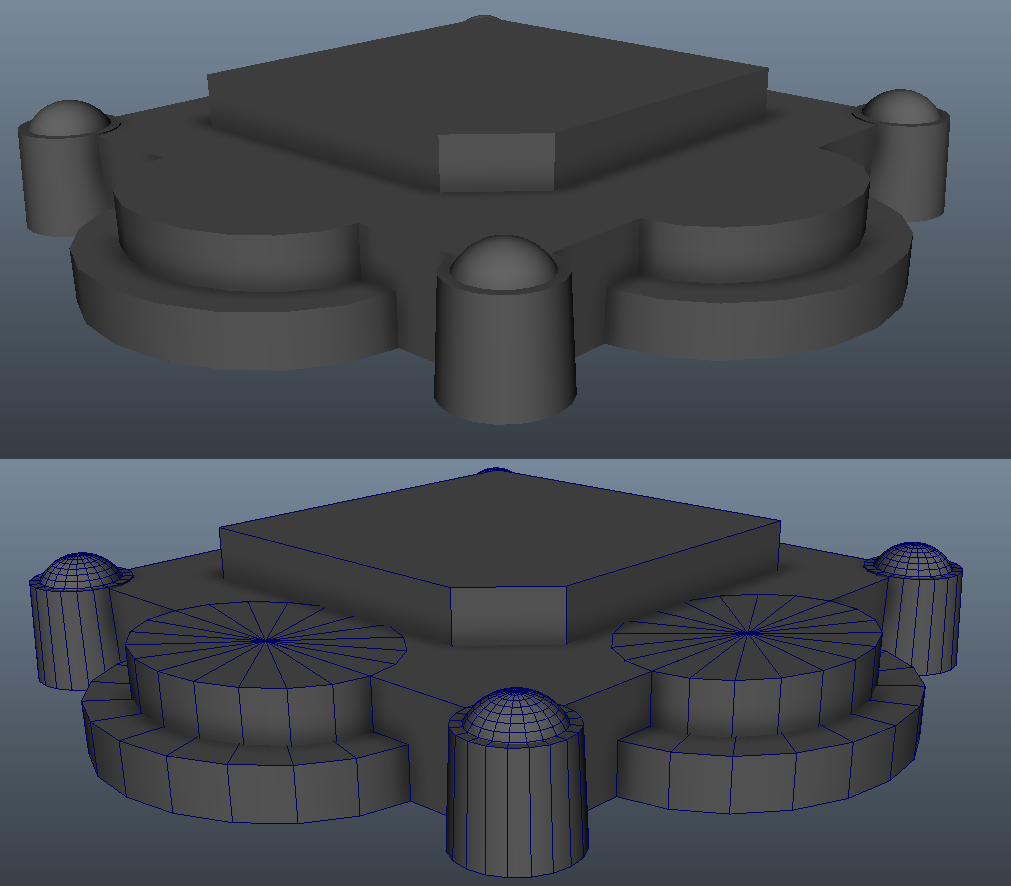
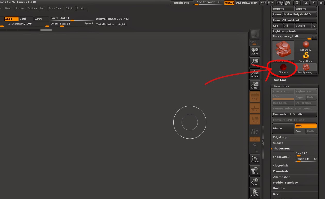
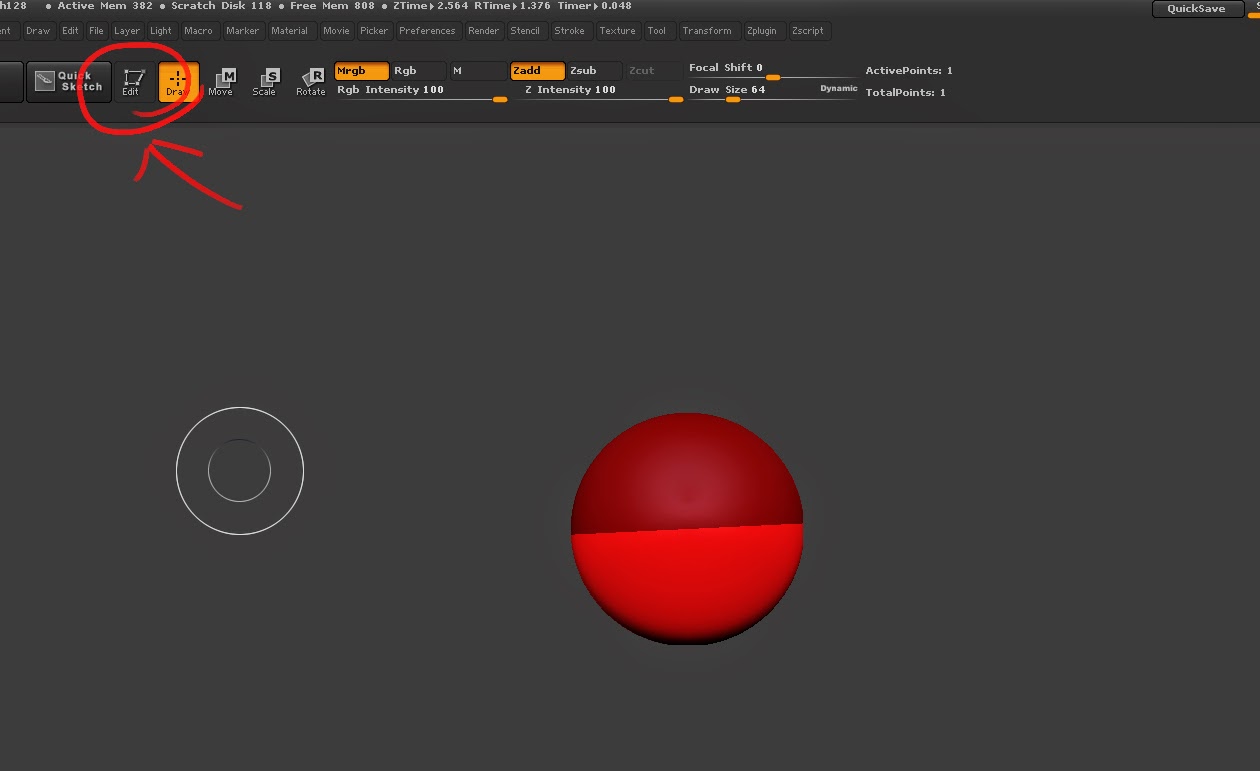
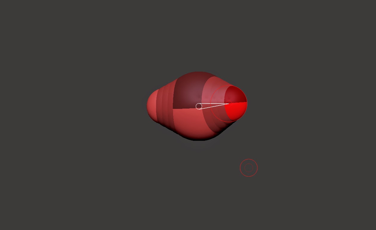
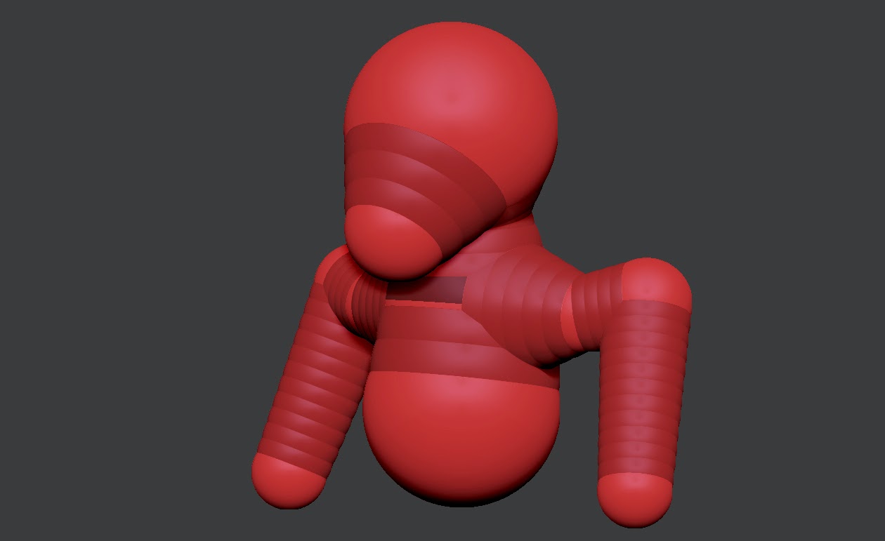
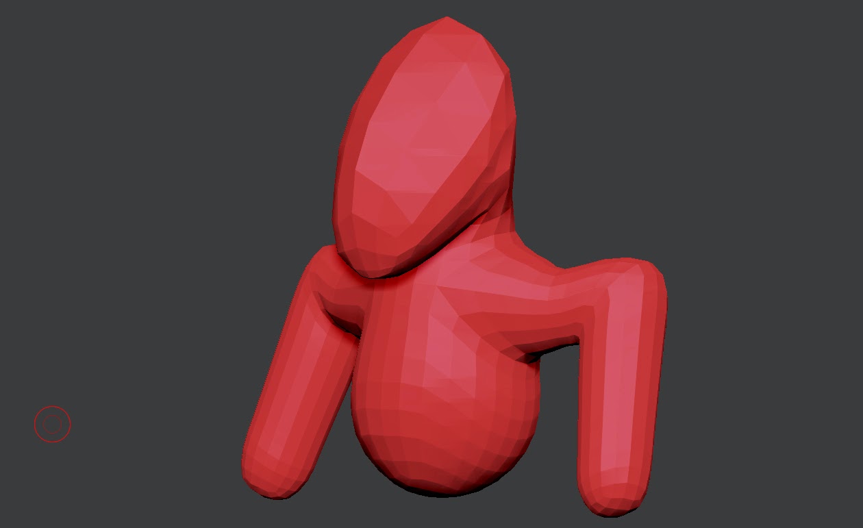
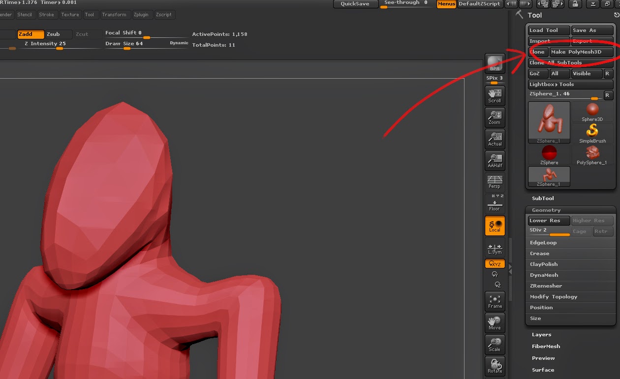
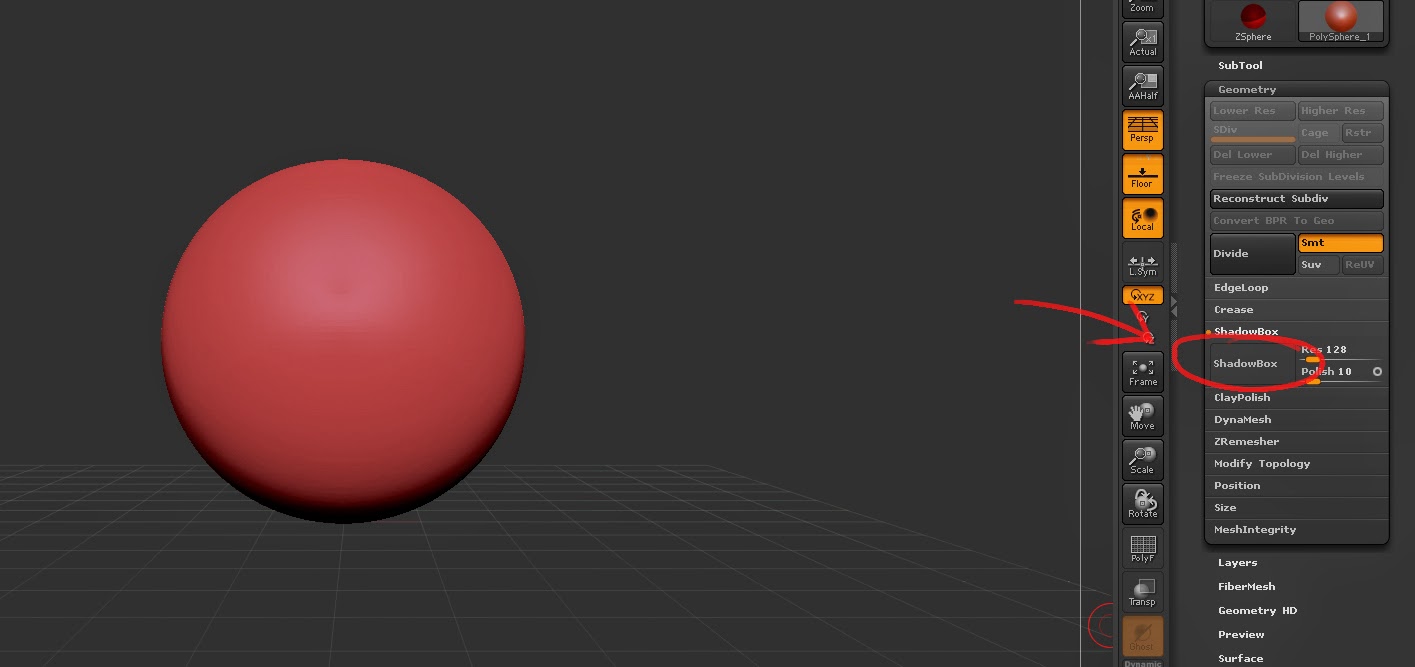
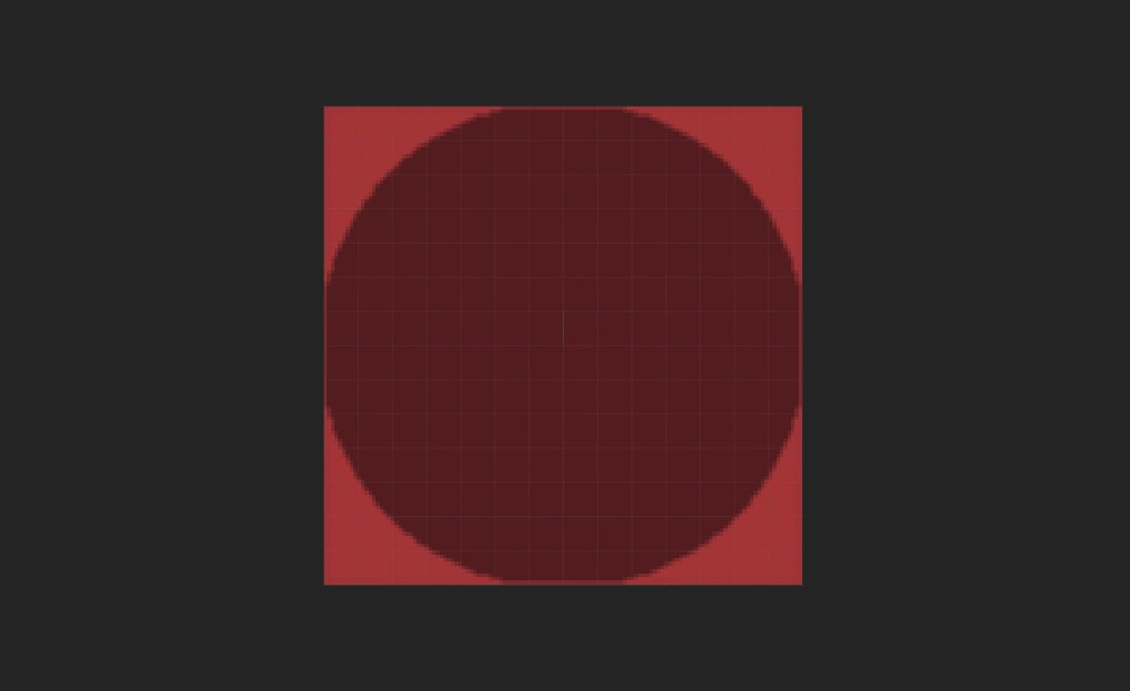
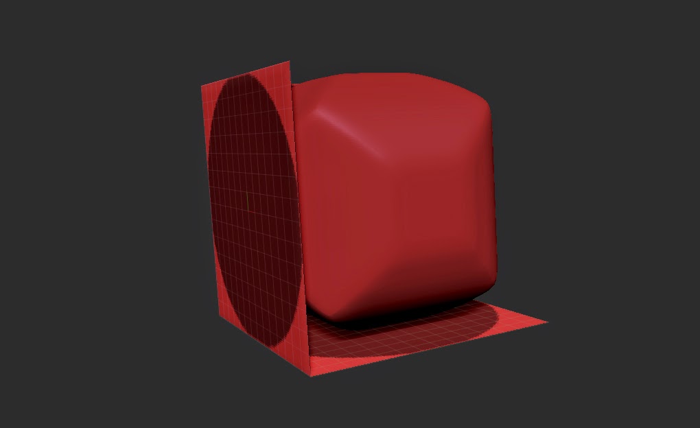
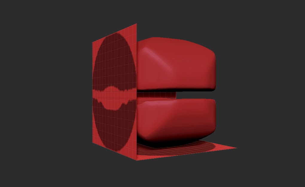
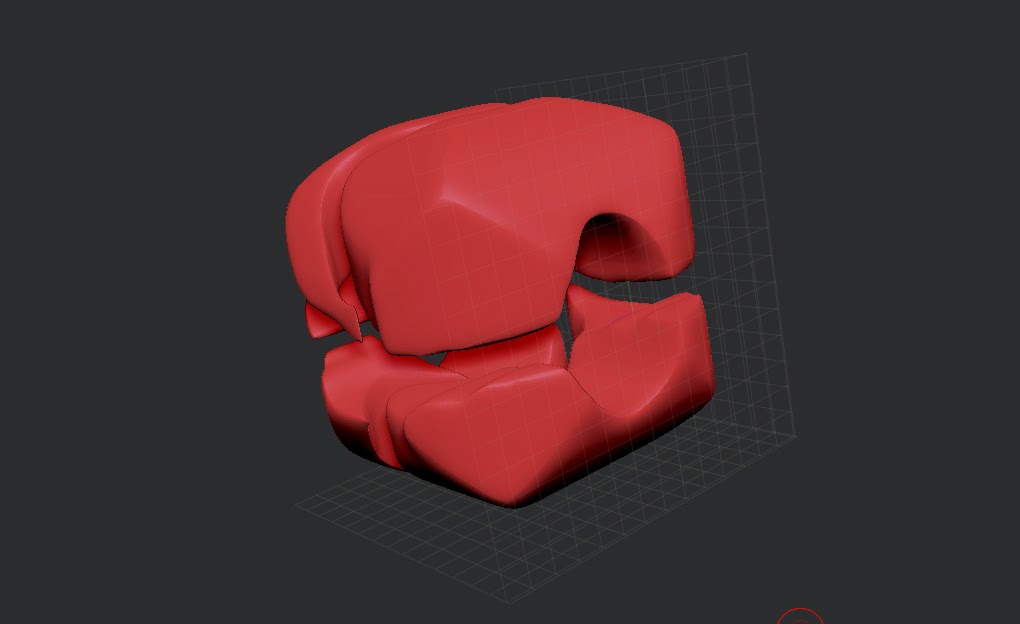
The second method is creating both a high-poly and low-poly model and projecting the detail of the high-poly onto a normal map using the low-poly model's UV unwrap. You can do this with xNormal or even directly in the sculpting program zBrush, with a few tweaks.


Despite the versatility of normal maps, they must be used in moderation. When creating them, one must consider how much the detail will stand out and whether it is possible to get away with faking it without people notice. Sometimes it is flat-out better to use geometry as these maps do not change the geometry and all illusion is lost once you see it from an angle that isn't intended.

Saturday, April 25, 2015

Understanding Different Texture Maps


In order to create life-like models, multiple different types of textures must be considered. Here, I'll be talking about three different maps which can control how an engine renders your model.


As shown above, there are five spheres, all with different basic textures assigned to it. The first 'basic' sphere has no texture assigned to it, and has just a simple 'blinn' material attached. Blinn is a better choice than the program's default lambert because you have a lot more choice with assigning different texture maps.

The second sphere, the diffuse sphere, is a sphere with just a diffuse texture assigned to it. The diffuse defines the colours of the model and is probably the most important for basic models.

The third sphere has only a specular texture assigned. The specular controls the intensity and colour of the lighting that is placed upon a model. This is best used to create materials convincingly, such as metals. It is also very useful for models with different materials within it, where you can define how shiny different parts of a model are. For example, with a sword, the metal sword blade will be a lot shinier than the hilt, which means the specular texture will be brighter.

The fourth sphere has a gloss texture assigned. The gloss defines how rough part of a model is. This texture is only greyscale as colour in this texture does not make any difference to the rendering of the model. The roughness is defined as how large the specular highlight - the shiny area - is.

The last sphere shows how the specular and gloss work together. As the gloss is larger here, the specular highlight is very large in areas where the specular texture is also white. Using and experimenting with these methods can create a wide range of materials.


In Autodesk Maya, these three textures are under various names. The Diffuse is fairly self explanatory, located under 'Common Material Attributes'. By clicking the checkered square on the side of the diffuse slider you can select the choice to choose a file to load. 

The other two textures are located under 'Specular Shading'. The Specular map can be accessed by using 'Specular Color', whilst the Gloss map can be accessed by using 'Eccentricity'. 


Friday, April 10, 2015

Learning to Think in Primitives

 It is well known that most modelling programs have an array of similar objects that you can start modelling with, going by the name of primitives. These primitives encompass the basic 3D shapes - the cube, cylinder, cone, sphere, plane and torus - as well as some unique ones like the teapot. Unlike in the real world, models are not required to have physics so you can mash them together almost however you like, but one useful skill for creating models from life is summarising shapes with primitives. This skill can save a whole lot of time and trouble when creating a model from life, as it gives you more chance to position things correctly without having to go in and modify single vertices, sides or faces.


Take this corner of a monument, for example. At first glance it looks very complex, but it can be summarised into different kinds of primitives, with only minor tweaks to a few of them.

This is a visual representation of what the shape could be, using just three different types of primitives. Red shapes are cubes, green being cylinders whilst blue are spheres. At this point in time, there is no need to worry about combining these and, as stated before, it doesn't matter that they clip into each other as physics does not apply in this situation.


This is the final result. In order to get some of the other shapes such as the flattened part on the top-most cube, I used the bevel tool. I scaled down some of the cylinders for the stairs to get a more accurate shape, but you can still see, in essence, the shape of each primitive put together to form a cohesive object. Learning this skill is invaluable to create accurate and well-built models quickly and efficiently, and practicing by drawing over images you have can help.

Wednesday, January 28, 2015

ZBrush - Lightbox

Aside from PolyPainting your mesh, there is a way to layer images directly onto your mesh. This method is called Lightbox.

Our egg
An egg texture
Today, let's paint an egg. The first image is the mesh we are going to paint on, and the second image is the egg shell texture we are going to apply onto our mesh.

The option to turn on Lightbox is in the 'Texture' tab

To start up Lightbox, you must go to the 'Texture' tab at the top of the window. Then, you must import your texture into ZBrush, where it will appear at the bottom of the available textures. With this texture selected, you must then press 'Add to Spotlight', which is the right-most button on the top row.

The wheel is a set of tools which will let you manipulate the texture directly

Your window will look something like this. The wheel that will show up is a group of tools which will allow you to manipulate the image, such as adjusting the opacity, how much it tiles, the contrast or the size. However, you don't need to do most of this.

Use your brush to paint the texture on
In order to activate painting mode (Making sure that your brush is set to RGB only and that 'Colorize' is on) simply press Z. The editing circle will disappear and your brush will re-appear. Simply edit the mesh to paint the texture on. You can also turn the mesh and re-apply from different angles if a specific area is stretched.

A happy egg!

To turn off the display, press Shift + Z. This will hide the texture and allow you to see your model.

Tuesday, January 27, 2015

ZBrush - Polypaint


Normally with texturing a model, a UV Map needs to be created onto which a texture is painted. However, there is another method that can be used within ZBrush, which has its perks and downfalls.

Polypainting is a method of colouring a model in which each vertex is assigned a colour. The colour will form a gradient with the vertices next to it. This method is also known as vertex painting. The main downfall of this method of texturing a model is that it requires a high-poly mesh to get any sort of detail out of it, which means it is not yet used within games.

Turn on PolyPaint by clicking 'Colorize', making sure to turn on the 'RGB' setting on your brush

To activate PolyPaint, you must go down to the 'PolyPaint' menu and hit 'Colorize'. You must also set your brush to paint 'RGB'. You should also turn off 'Zadd' so that you only paint colour, and avoid modifying the mesh.

Change your colour with the palette

You can change the colour you are painting on your mesh by using the colour palette on the left side of the screen. Normally, this would colour the entire mesh, but since PolyPaint is turned on, this will no longer happen to this SubTool. If you are working with multiple Subtools, this will change the colour of them unless they are already painted.

Lots of gruesome texture

Polypaint is easy to use since you can paint right onto the model. You can also use it with brushes to add texture. This is achieved by turning 'Zadd' on whilst painting.

No longer looking so sharp...

However, one thing to be aware of is that detail will be lost if you go down in subdivisions. This can be avoided by using UV Maps, though this will mean you will have to map your model.

Sunday, January 25, 2015

ZBrush - Alphas

Sometimes the standard brushes in ZBrush do not quite get the effect you want in an efficient amount of time. A way to improve this is by using alphas on your brushes.

An alpha in image format, before being imported

This is one way of creating an alpha. Alphas in ZBrush work by using a displacement map (the lighter the area, the more that is displaced) which you can import in. You can make these yourself by just using a greyscale image.

A plain mesh, which could do with some detail
Here is a sphere with a little sculpting work done on it, but it is feeling a little empty, so it's time to add some surface detail.

Select the import button and navigate to your saved alpha, then import it. It will appear on the bottom row of the Alphas list
Select the 'Alpha' box on the left side of your screen, and a window should open up. In this window, you must select the 'Import' button at the bottom of this window. This will allow you to navigate to your image file. ZBrush is compatible with .PSDs, JPGs and most other formats, but so far I have not been able to successfully import a PNG file, so avoid using these if possible.

Now you're thinking with alphas!
Now select your imported Alpha, which should appear in the bottom row of your opened window. Now you are able to use the changed brush to add more detail onto your mesh. You can also change the Stroke of the brush to apply it in a different way. DragRect is best used for singular detail, whilst Dots is better used for larger patterns.

Friday, January 23, 2015

ZBrush - Topology and ZRemesher

Whilst sculpting in ZBrush, it is likely that DynaMesh has been used to create the base form, upon which subdivisions have been created to add detail. However, as explained before, DynaMesh does not take topology into consideration when dividing the object, which can be an issue in game assets which are intended for rigging and animating.

Looks normal...

At first, this sculpt looks absolutely fine. You would probably be happy with this level of detail unless you were going into super high-level detail work, however...

Awful topology
There is no efficient topology because of the use of Dynamesh. Trying to animate or pose this sculpt will prove extremely difficult to get lifelike movement. There is also the issue that the amount of polygons is very high. In this image there is about 1.312 million active points. Putting this into a game engine (in 2015) with other assets will more than likely put a severe strain on the system.

The difference between good and bad topology
Here is a diagram detailing what good and bad topology is. Good topology follows the muscles of the face, so as to make it easier to animate fluidly. So, there are loops around the mouth and eyes to that they are easier to open and move about. Good topology should minimise the areas of 'pinching' (where more than 4 or 5 edges meet) as well as tearing whilst animating.

So, how do we fix this in ZBrush?

Thankfully, there is a tool within ZBrush which will analyse your mesh and create a more efficient topology for you. However, it is not perfect and sometimes you will have to make some adjustments yourself.

Hit the ZRemesher button. Don't forget to duplicate your SubTool first

Before beginning the re-topologising process, you should duplicate your SubTool. This will be useful later.

The tool ZRemesher can be found under the 'Geometry' menu in your toolbox. As stated before, ZRemesher will analyse the mesh, looking at possible curves as well as peaks and valleys and use those to create a more efficient topology. The target amount of polygons can be changed at 'Target Polygon Count' where the number (default 5) is multiplied by 1000. The other options do not need to be touched as of right now.

Much better topology

With ZRemesher, the topology of the model is vastly improved. However, it has lost most of its detail, going down from 1 million points to just 7 thousand. Despite this, you are able to get this detail back.

By subdividing the mesh and Projecting the Dynameshed sculpt onto your ZRemeshed sculpt, you can retrieve the detail from the Dynameshed sculpt.

Projection will allow you to take detail from your Dynamesh and put it into your ZRemeshed sculpt whilst maintaining topology
To do this, you must have your Remeshed sculpt selected, with the visibility of the Dynameshed sculpt turned on. Then, lower in the SubTool menu, there is the option to 'ProjectAll'. This will check from all points at a specific radius out on the Remeshed sculpt and, if it collides with the Dynameshed sculpt it will move the point to the position. Since our mesh is very similar we do not need to touch 'Dist', however this can be increased if some parts of the Projection are too far away. However, increasing it too much will cause some tearing.

Barely any visual difference, for under one quarter of the points!
As shown above, ZRemesher is very useful for cutting down on the active points with minimal visual difference within the model. However, it is better to use this tool when you are done with the overall shape of the model, as the topology will change depending on the shape, meaning that your ZRemeshed model is no longer as efficient and you may end up needing to Dynamesh over it.

Wednesday, January 14, 2015

ZBrush - ZSpheres

Unlike most digital modelling programs, with ZBrush it is very easy to start from nothing. One of the ways to achieve this is by using ZSpheres, which allow you to create rudimentary forms out of spheres.
You must select the ZSphere tool from the tool palette

To access ZSpheres, you must go to the tools palette and select the ZSphere tool from the palette. You then draw one out onto your canvas. At this moment you are in 2.5D drawing mode, so you must only draw 1 sphere.

Drag out only one sphere, then hit the 'Edit' button in the top left

Now, after drawing the sphere out, you must click the 'Edit' button to enter edit mode. This is very important, so do not skip this step!

To add additional spheres, draw them by clicking and dragging on an existing sphere

Now you can create your form. By clicking on the Sphere, you can draw additional spheres. The Move tool (located next to the Edit button shown previously) will move spheres around, whilst scale will scale them. One thing to keep in mind is that symmetry is not turned on by default, though you can easily toggle it by pressing X.

Creating a basic shape is very quick and easy with ZSpheres
Press 'A' to preview your mesh

After you get a form created, you can hit A to preview your mesh outside of ZSpheres. You can also edit in preview mode.

Pressing 'Make PolyMesh3D will turn your mesh permanent
To turn your model permanently into a mesh, you must press the Make PolyMesh3D button. This will allow you to do anything to your mesh that you would be able to do with a primitive, such as enable DynaMesh. However, once you hit this button, you must re-enable symmetry by pressing x. You can now work on your newly created mesh like you would a sphere primitive.

Sunday, January 11, 2015

ZBrush - Shadowbox

Within ZBrush, there are multiple different ways to start off a sculpt. One of these methods is Shadowbox. Shadowbox has its perks but also has its downfalls, which will be demonstrated below.

The Shadowbox button is located under the 'Geometry' tab
To access Shadowbox, you must press the button located under the 'Geometry' menu on the right of the screen.

This is the view you will get right after clicking 'Shadowbox'
Rotating the mesh to the side, you will see the object there
You will be presented with your object being mapped onto 3 different planes, one for each axis (x, y, z). Shadowbox calculates where lines intersect and creates vertices there, creating a shape from 3 flat images. It is also possible to import images from another program and use those to create an object.

Removing part of the mask will affect the object directly
You can edit the pre-existing shape by using the mask tool (Ctrl) to add to the silhouette, and remove mask tool (Ctrl + Alt) to take away from the silhouette.

After messing around for a short while...
Shapes can be created pretty quickly with Shadowbox, however there is the issue in which shapes can become blocky and hard to manipulate effectively, though this can be fixed by going in with sculpting tools after achieving your desired shape with Shadowbox. Simply press the button in 'Geometry' again to turn it off.

Friday, January 9, 2015

ZBrush - Dynamesh and Masking

A perfecly normal sphere, with Polyframes (Shift F) turned on to show the polygonal geometry
Whilst sculpting in ZBrush is very easy to get the hang of, often you will run into a snag where you have stretched the polygons too far and they will become jagged and lower in resolution.

Jagged edges have formed because the resolution is too low
Above is an example of where the surface of the model has been pulled out too far and the resolution on the part that has been pulled out has decreased. However, there is a solution that will rectify this problem and allow for a more seamless sculpt.

The DynaMesh sub-menu can be located in the Geometry menu
DynaMesh works by creating equally spaced lines both vertically and horizontally across the model. Where these lines intersect with the model, a point will be created so that it forms into an evenly spaced model that is ready to be sculpted upon. As shown above, there are many options, however you should only really need to look at the DynaMesh button and the resolution. Changing the resolution changes how much the mesh gets divided, introducing more points than it would at a lower resolution.

The mesh has been DynaMeshed
You can activate DynaMesh by either pressing the button or, whilst sculpting with the DynaMesh button already pressed, by dragging a mask outside of the model. However, there are many drawbacks to using DynaMesh. DynaMesh does not consider topology so every area will be as detailed as everywhere else. There is also the issue that finely sculpted features will be blocky unless you increase the resolution.

When the masking tool (Ctrl) is selected, the cursor will turn yellow
Masking (with the Ctrl key) can also be used to obscure parts of the model from editing. This will affect tools like DynaMesh as well as regular sculpting. There are many different things that can be done with the Mask tool:
  • When you are hovered over the mesh, the Masking tool will default to a pen, allowing you to draw on the mask.
  •  If you start creating a mask from outside the selection of the mesh, you will default to a rectangular mask.
  • Dragging a mask outside the mesh while there is a mask applied will clear the mask. 
  • Clicking outside the mesh will invert the mask.
  • Clicking on the mesh will soften the mask.
  • Clicking on the mesh whilst subtracting (hold the Alt key) will sharpen the mask.
The darkened area of the mesh is where the mask is
Keep in mind that masked areas will not be affected by any tool, including even subdividing, so make sure to subdivide your mesh before you mask or you will end up with a very un-even resolution, unless that is your intention!